hardware design, assembly, and instrumentation
Custom hardware design, assembly, and instrumentation for acoustic experiments, including impedance tube construction and measurement setups.
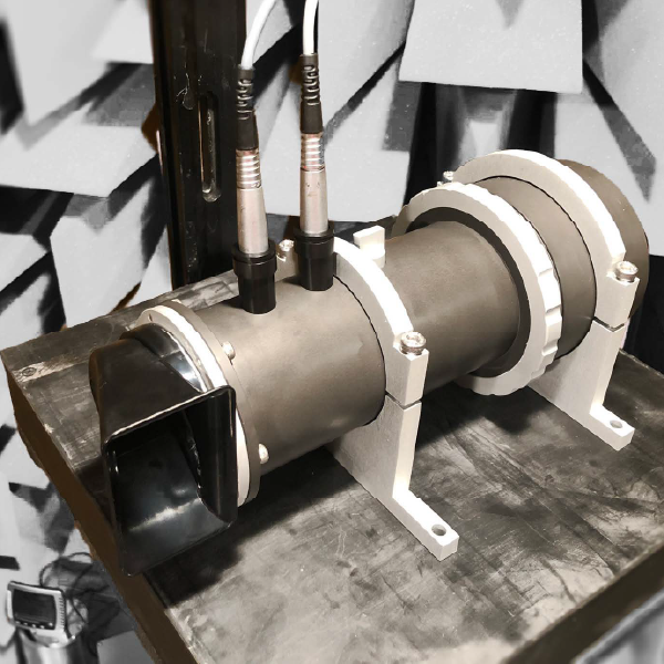
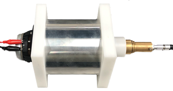
Custom-designed impedance tube
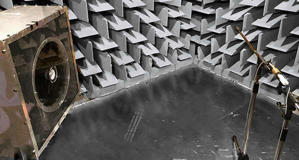
To measure the acoustic input impedance of an automotive horn, a custom-designed impedance tube was developed and fabricated in compliance with ISO 10534-2. This setup enabled reliable broadband impedance characterization consistent with industrial standards.
Standard
ISO 10534-2:2023 Acoustics — Determination of acoustic properties in impedance tubes, Part 2: Two-microphone technique for normal sound absorption coefficient and normal surface impedance
Experimental Setup
- Custom-designed impedance tube complying with ISO 10534-2
- Car shell horn (device under test)
- Spectrum analyzer, measurement microphone
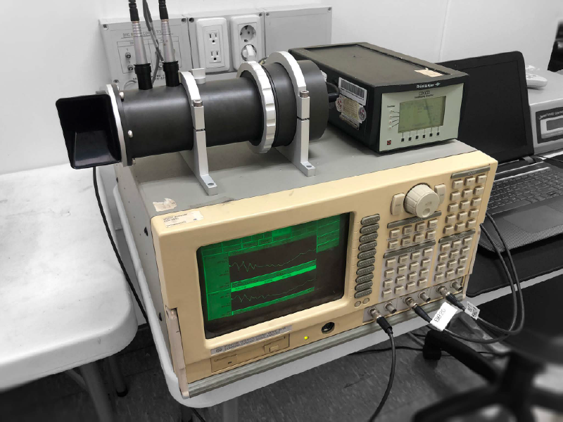
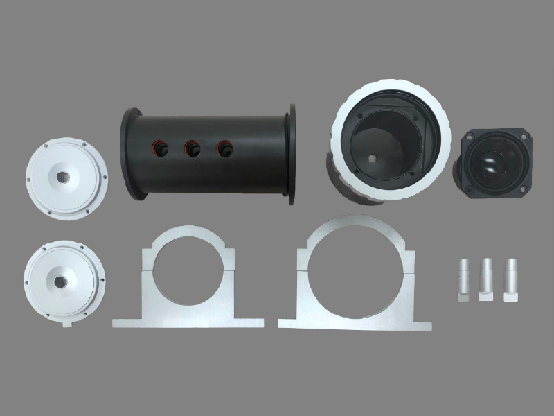
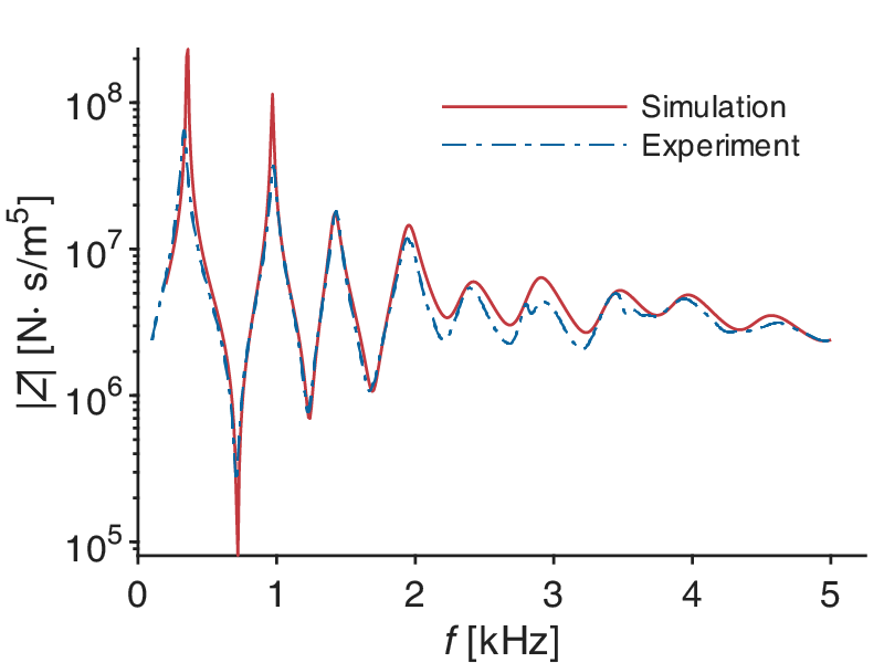
The measured acoustic input impedance of the automotive horn showed good agreement with FEM predictions, validating the accuracy of the impedance tube design and measurement procedure.
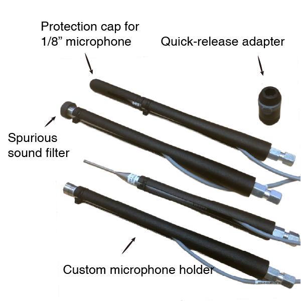
Custom microphone holder
To prevent acoustic interference arising when multiple microphones are placed simultaneously in the same spatial position, measurements were conducted sequentially. Custom holders were fabricated so that different microphone types could occupy exactly the same spatial location during measurements(Kim† et al., 2025; Kim et al., 2025).
Experimental Setup
- Fabricated a custom microphone holder via MJF 3D printing to allow sequential use of 1/8-inch and 1/2-inch microphones at identical spatial positions
- Employed a quick-release adapter to enable fast microphone exchange while maintaining alignment
Results
Achieved consistent spatial positioning of microphones, eliminated mutual interference, and ensured reliable characterization of both ultrasonic and audible fields with minimal system variability.
Hands-on Experience in Transducer Assembly
Establish executable assembly plans, acquire proper knowledge of transducer integration, and develop appropriate tools for reliable assembly.
Technical Skills
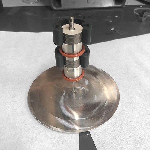
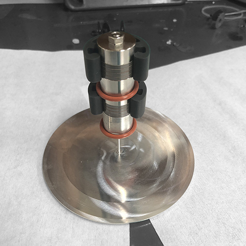
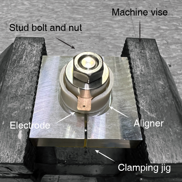
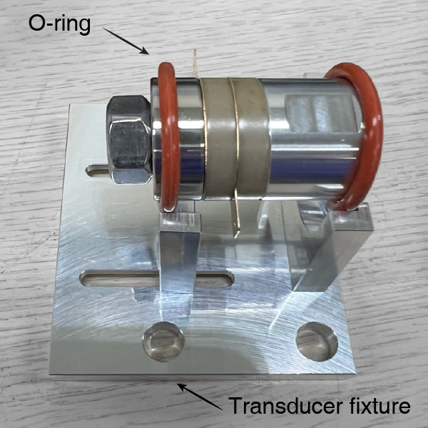
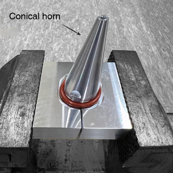
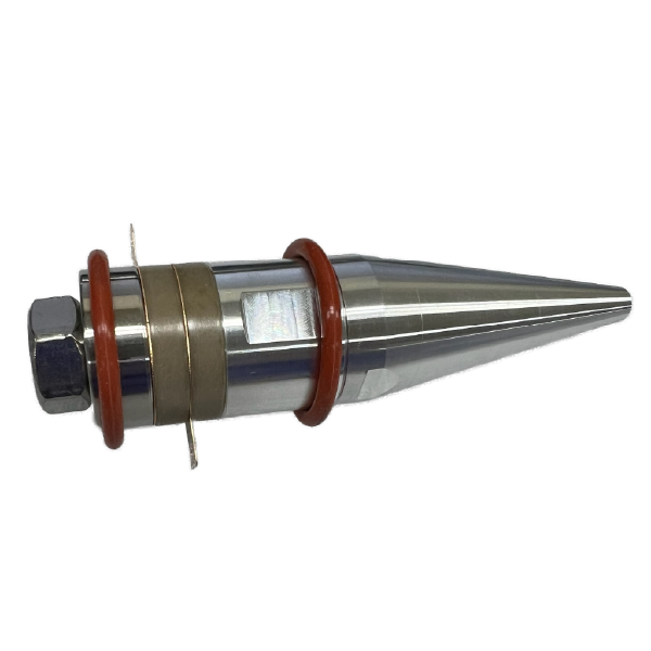
- Utilized a 3D-printed alignment jig to precisely align transducer parts and electrodes, designed to apply radial pre-stress and secure proper concentricity during piezoelectric ultrasonic transducer assembly.
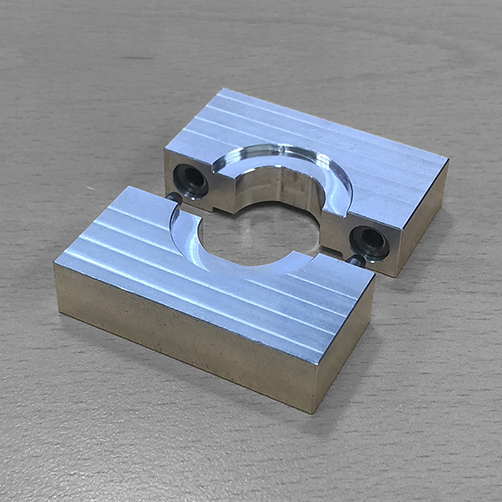
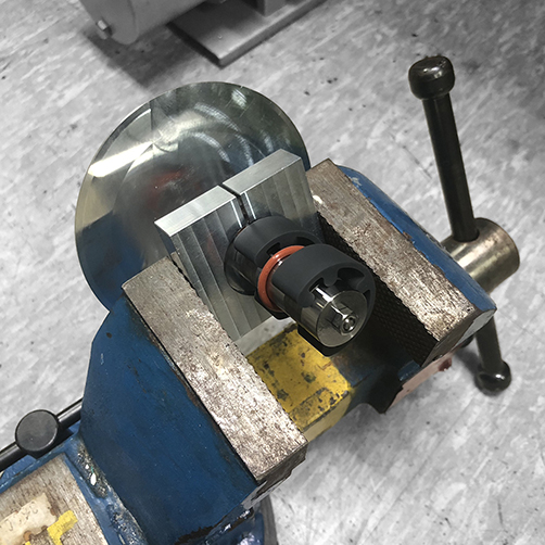
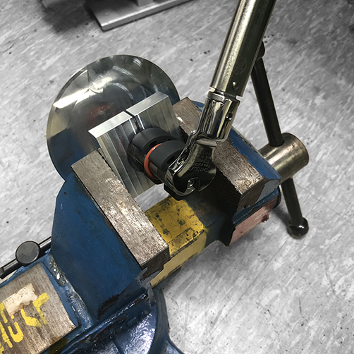
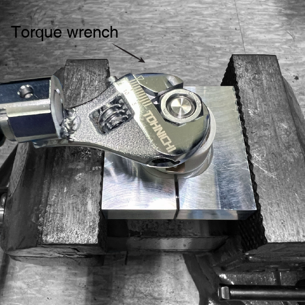
- Designed and fabricated a wrench-flat clamping jig enabling controlled preload application using a torque wrench.
- Applied specially designed fasteners to prevent thread stripping during assembly and to withstand both preload and dynamic loads during operation.
Results
- Established a consistent assembly process, with assembled ultrasonic transducers demonstrating good agreement between experimental measurements and simulation results.
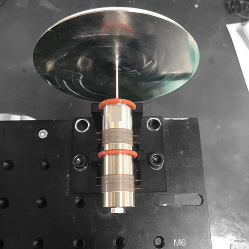
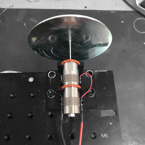
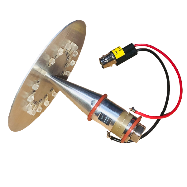
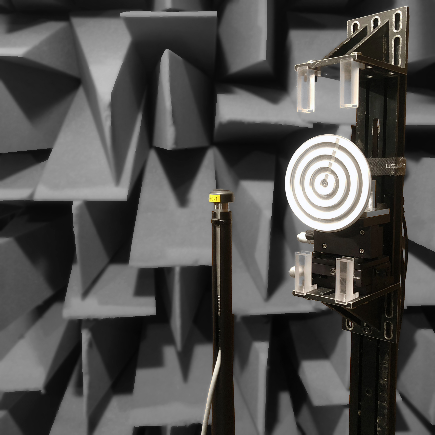
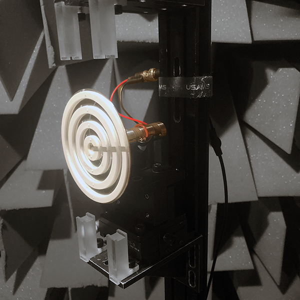
Stepped plate parametric array loudspeaker(Kim et al., 2025)
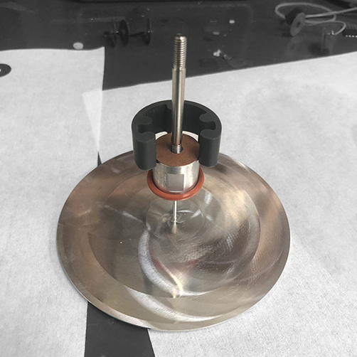
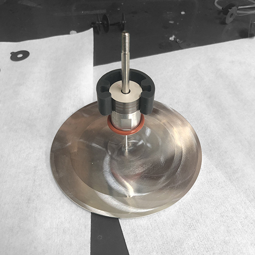
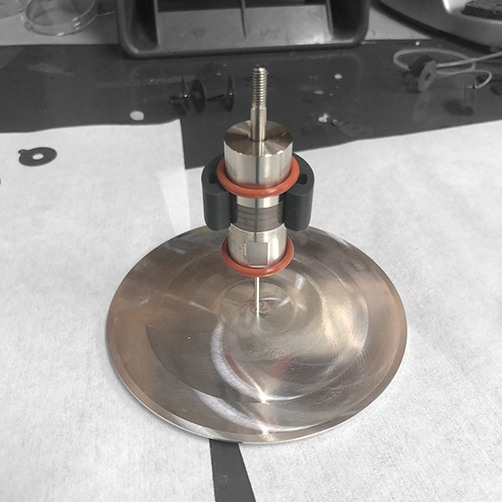
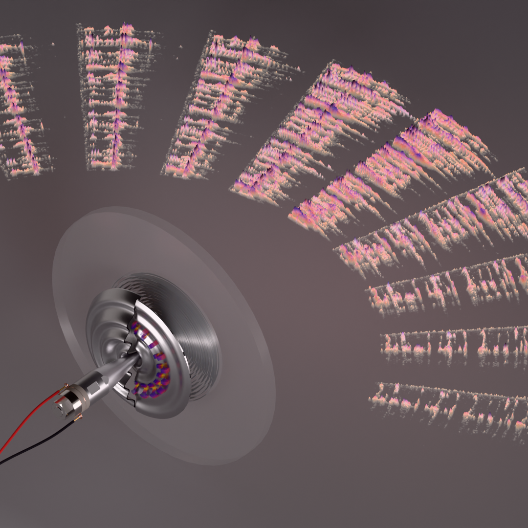
Metamaterial-integrated parametric array loudspeaker(Kim† et al., 2026)
Circuit Implementation for Demonstration
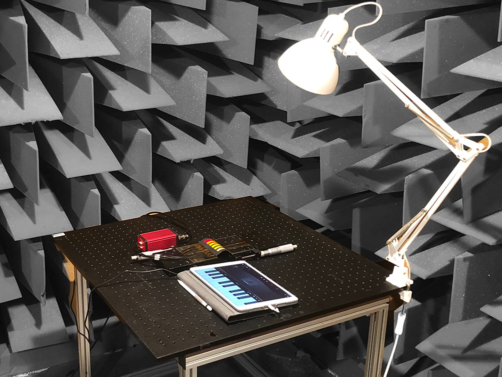
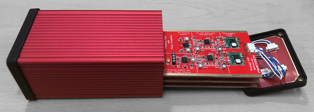
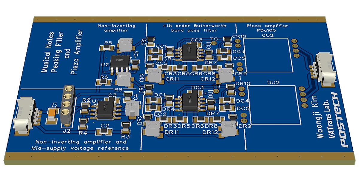
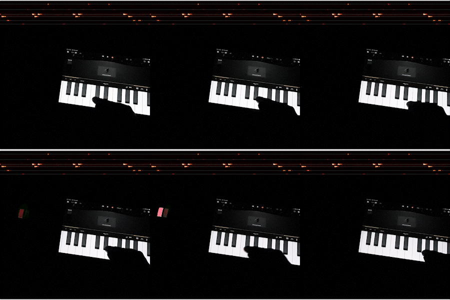
To design and implement the driving circuit for demonstration, including bandpass filters and piezo amplifiers, enabling frequency-selective sound generation synchronized with light emission. The circuitry was designed such that musical inputs from a piano app on a tablet PC directly drive flexible alternating-current electroluminescent (ACEL) devices, realizing an interactive sound-and-light demonstration.(Park† et al., 2024)
Technical Skills
- Tablet PC's output signal characterization, Circuit configuration & design, Component selection, PCB layout, Assembly, EMC consideration
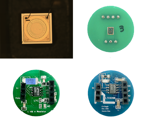
MEMS Microphone Analog Interface
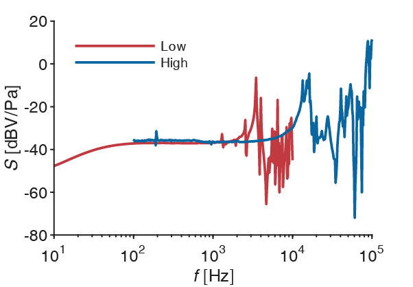
Investigate MEMS microphone analog interfaces (voltage and charge amplifiers), evaluate the effect of parasitic capacitance from packaging and preamplifier circuits, and apply guard ring strategies to enhance sensitivity and SNR.
Technical Skills
- Designed and fabricated custom interface PCBs for MEMS microphone die characterization.
- Identified parasitic capacitance sources using an impedance analyzer and validated their effects through LTspice circuit simulations.
- Implemented guard ring connection via metal lid and verified sensitivity improvement experimentally.
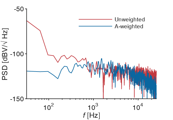
- Characterized MEMS microphone performance in terms of sensitivity, noise floor, and SNR(A).
Related works
2026
- Dual-domain metamaterials co-integrated with a compact ultrasonic transducer for highly directional audio generationNature Communications, May 2026Media coverage International
EurekAlert!
Tech Xplore
Nanowerk
Hackster
Ny Teknik
Techno
Digital Trends
Interesting Engineering
Gadget Review
Mapping Ignorance
DongA Science Korean
Yonhap News
The Dong-A Ilbo
The Kyunghyang Shinmun
YTN Science
Newsis
KPI News
Daegu MBC
Pohang MBC
TBC
Joongdo Ilbo
KIPOST
Newsworks
Gyeongbuk Maeil
Gyeongbuk Shinmun
Gyeongbuk Domin Ilbo
Gyeongbuk Ilbo
Daekyung Ilbo
Veritas Alpha
Korea University News Video
 YTN Science
  Pohang MBC Radio
 KBS 1Radio
2025
- An Accurate Measurement of Parametric Array Using a Spurious Sound Filter Topologically Equivalent to a Half-Wavelength ResonatorApplied Acoustics, Dec 2025
- Design, Analysis, and Experimental Validation of a Stepped Plate Parametric Array LoudspeakerThe Journal of the Acoustical Society of America, Sep 2025
2024
Disclaimer: The contents provided on this page are for personal, academic, and non-commercial use only. Copyrights and all other rights are maintained by the respective authors or publishers. These materials may not be reposted without the explicit permission of the copyright holder.