mechanical vibration characterization
Mechanical vibration characterization of radiating plates using laser Doppler vibrometry (LDV) for transducer validation.
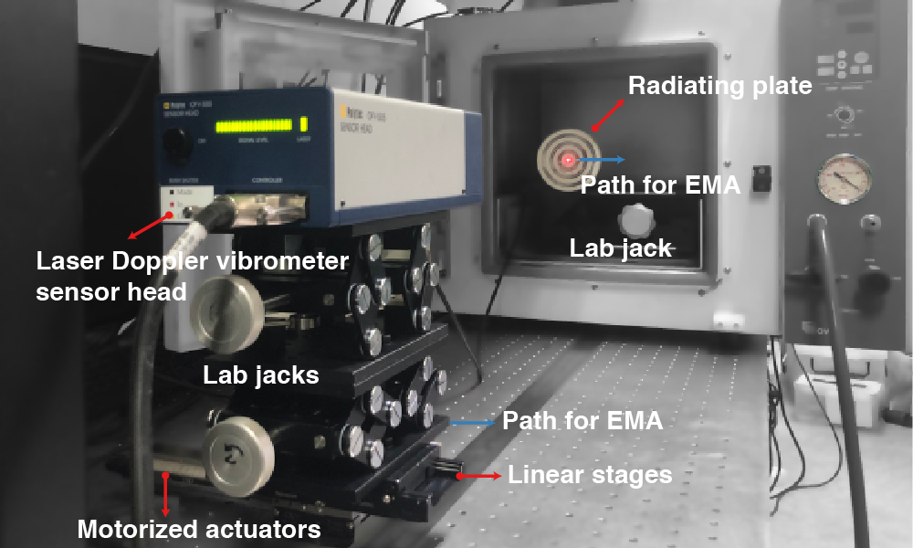
Mechanical vibration characterization
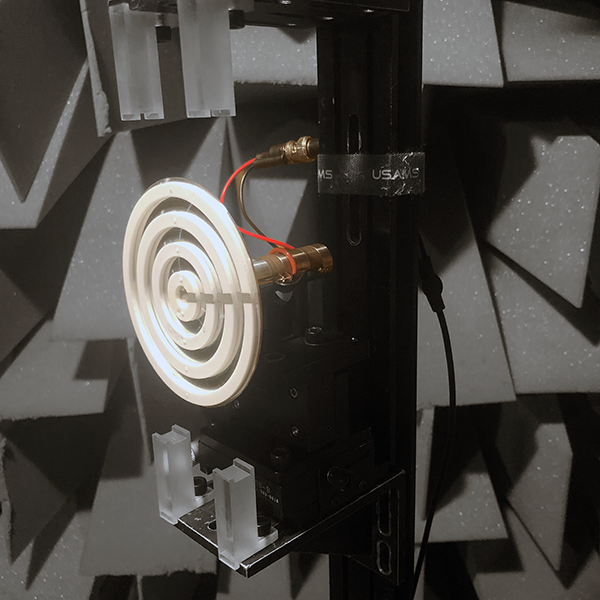
Using MATLAB-based automated control, single-point LDV measurements were performed to obtain not only the frequency response of the radiating plate but also its experimental modal analysis (EMA). The experimental results were compared with FEM simulations, and the underlying mechanism of the previously unreported combination resonance in stepped plate parametric array loudspeakers was first identified (Kim et al., 2025).
Experimental Setup
- MATLAB-based automated measurement program
- Spectrum analyzer, single-point laser Doppler vibrometer, power amplifier, stage controller, linear stages
Technical Skills
- Orchestrated the spectrum analyzer, laser Doppler vibrometer, power amplifier, and stage controller from a single MATLAB program, so that once the setup had been aligned an entire modal scan ran to completion unattended.
- Removed operator action between grid points, holding the excitation and acquisition settings identical across the whole scan so that the measured mode shapes could be compared against FEM predictions on equal terms.
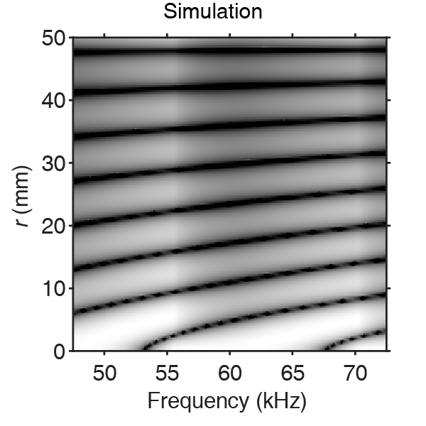
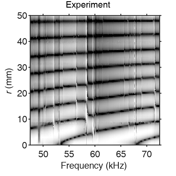
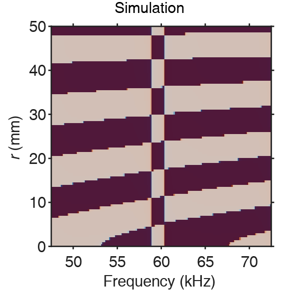
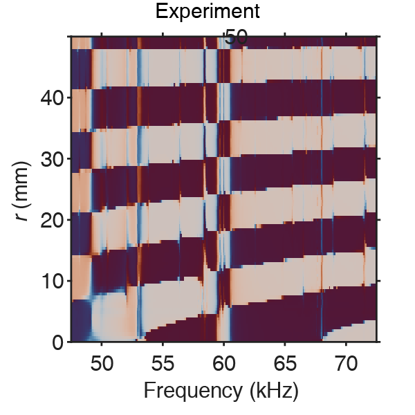
The EMA of the radiating plate around the 8th eigenmode frequency showed close agreement between FEM predictions and experimental measurements, validating the accuracy of the modeling approach.
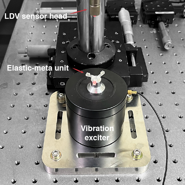
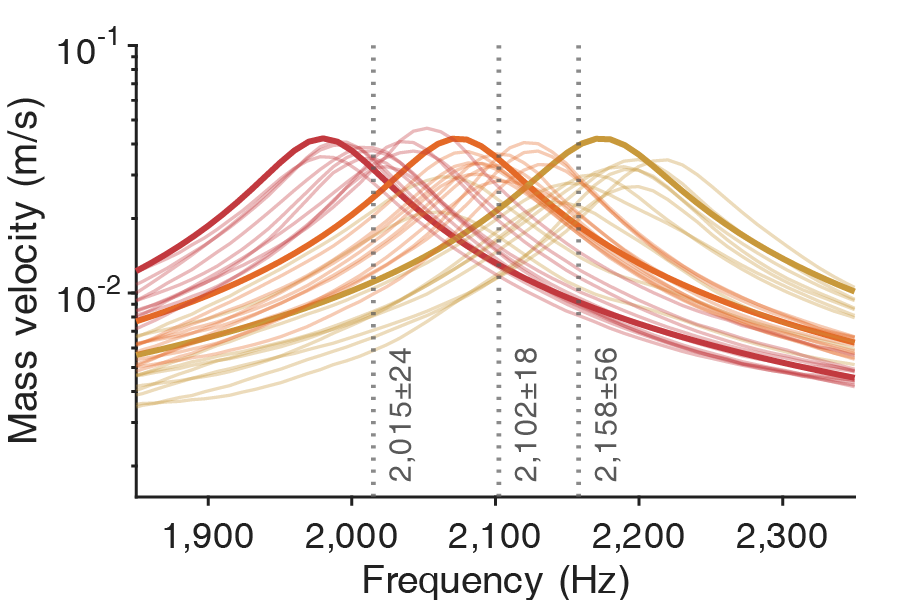
Locally Resonant Metamaterial Characterization
To estimate the effective properties of a 3D-printed locally resonant metamaterial (LRM) and use the identified values to redesign it to meet the required resonant behavior.(Kim† et al., 2026)
Experimental Setup
- Spectrum analyzer, single-point laser Doppler vibrometer, power amplifier, vibration exciter
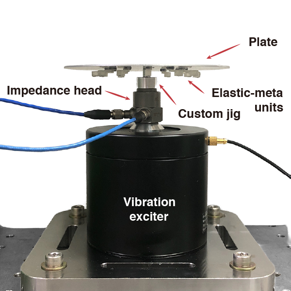
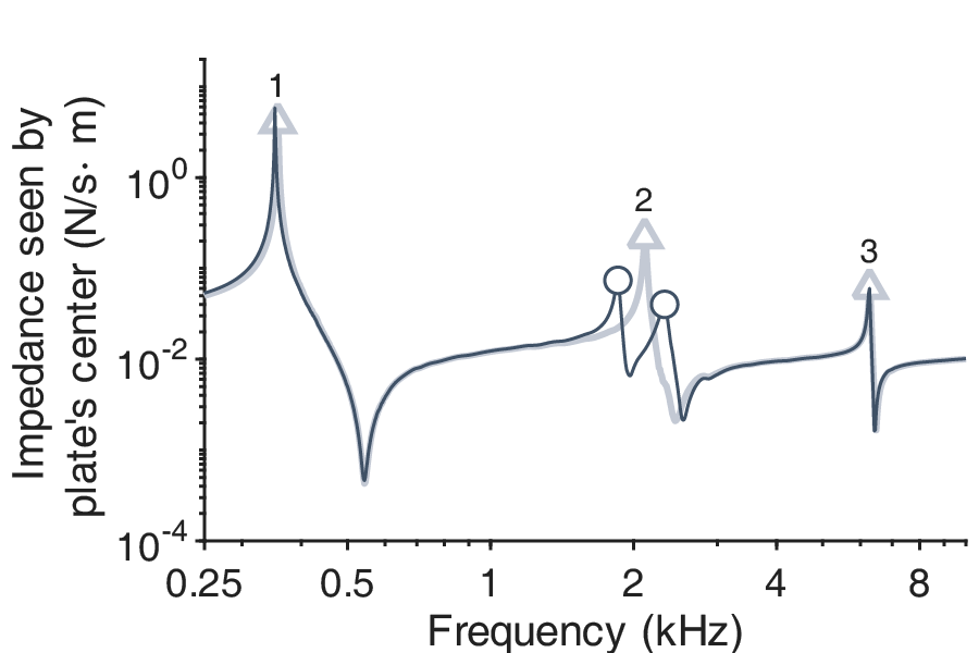
Plate Impedance Characterization
Plate impedance characterization was performed to evaluate the frequency-dependent dynamic behavior of the radiating plate with and without the locally resonant metamaterial.(Kim† et al., 2026)
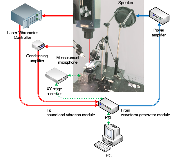
Experimental Setup
- Spectrum analyzer, power amplifier, vibration exciter, impedance head, custom jig (Carefully designed to ensure rigid support while minimizing any influence on the measurement results.)
Miniature Diaphragm Characterization
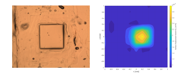
Because the compliance of thin and tiny polymer diaphragms (micrometer thick and sub-millimeter diameter) critically determines acoustic sensor performance, a precise measurement methodology based on passive excitation was established. Diaphragm compliance data were obtained and the methodology was validated by comparing measurement results with FEM simulations.
Experimental Setup
- LabVIEW-based automated measurement program
- Note that constructing a pressure chamber for controlled passive excitation would further improve measurement reliability and remains as future work.
Related works
2026
- Dual-domain metamaterials co-integrated with a compact ultrasonic transducer for highly directional audio generationNature Communications, May 2026Media coverage International
EurekAlert!
Tech Xplore
Nanowerk
Hackster
Ny Teknik
Techno
Digital Trends
Interesting Engineering
Gadget Review
Mapping Ignorance
DongA Science Korean
Yonhap News
The Dong-A Ilbo
The Kyunghyang Shinmun
YTN Science
Newsis
KPI News
Daegu MBC
Pohang MBC
TBC
Joongdo Ilbo
KIPOST
Newsworks
Gyeongbuk Maeil
Gyeongbuk Shinmun
Gyeongbuk Domin Ilbo
Gyeongbuk Ilbo
Daekyung Ilbo
Veritas Alpha
Korea University News Video
 YTN Science
  Pohang MBC Radio
 KBS 1Radio
2025
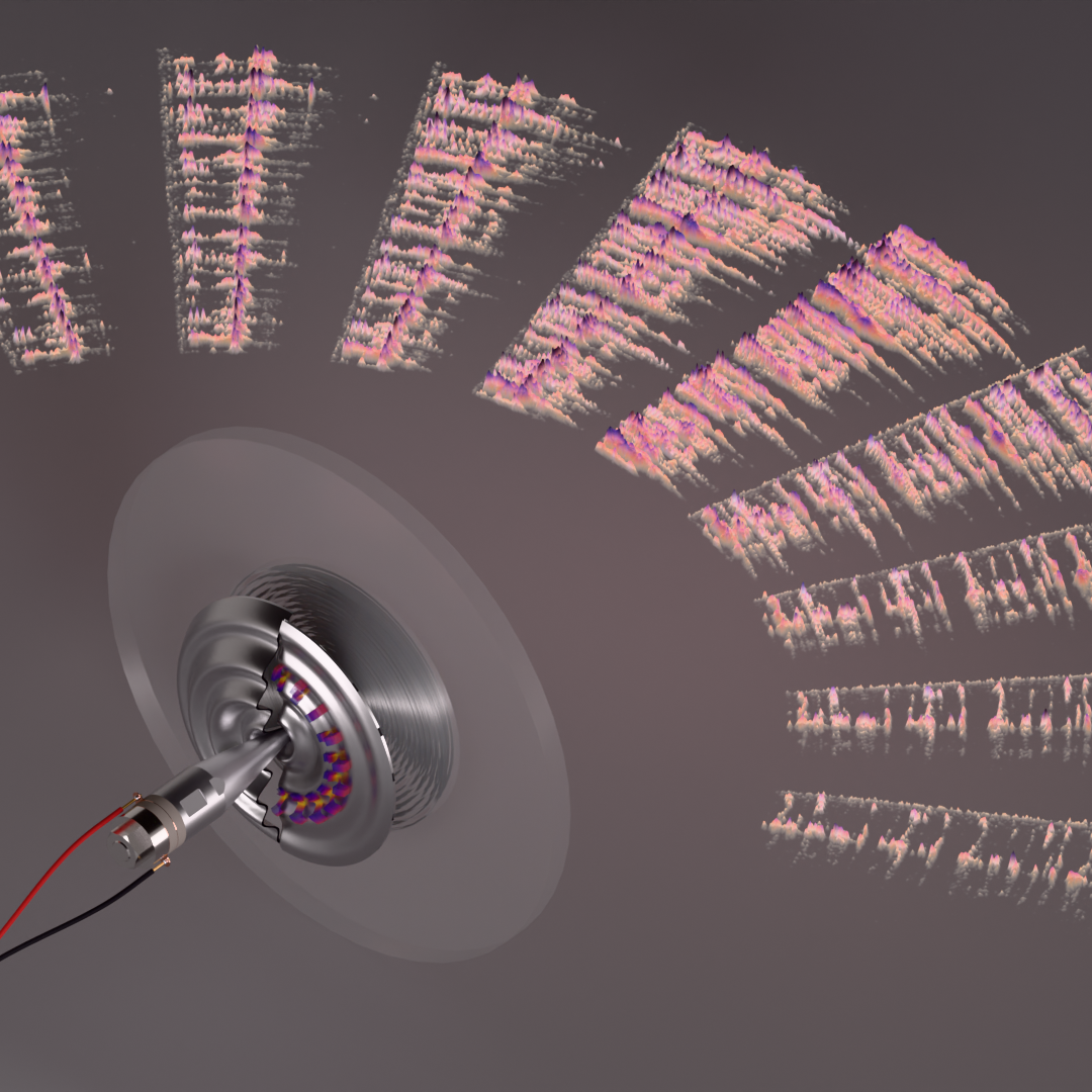
- Design, Analysis, and Experimental Validation of a Stepped Plate Parametric Array LoudspeakerThe Journal of the Acoustical Society of America, Sep 2025
Disclaimer: The contents provided on this page are for personal, academic, and non-commercial use only. Copyrights and all other rights are maintained by the respective authors or publishers. These materials may not be reposted without the explicit permission of the copyright holder.